Coil Winding Machine Applications
Coil winding machines typically involve two coordinated motion control axes. Axis 1 is the rotation axis which runs at a constant speed during winding for each coil. Axis 2 moves the wire as an “electronic gear” or “electronic cam” function of the Axis 1 position. For each coil made, Axis 1 motion is simply start from zero speed, run at constant speed, and stop at a programmed deceleration at the end of the winding operation for each piece. At the same time, Axis 2 makes the “slave” moves relative to the Axis 1.
- If the coil is a helical coil winding type application, the Axis 2 simply runs at a fixed gear ratio with respect to Axis 1 actual position.
- If the coil is to be placed in certain slots on the shaft as function of position of the Axis 1 in each rotation, the Axis 2 moves a certain distance within a certain angular motion of the Axis 1, then stops. This is essentially a cam motion synchronization between two axes. For different coil products, there are also expected to be different cam functions.

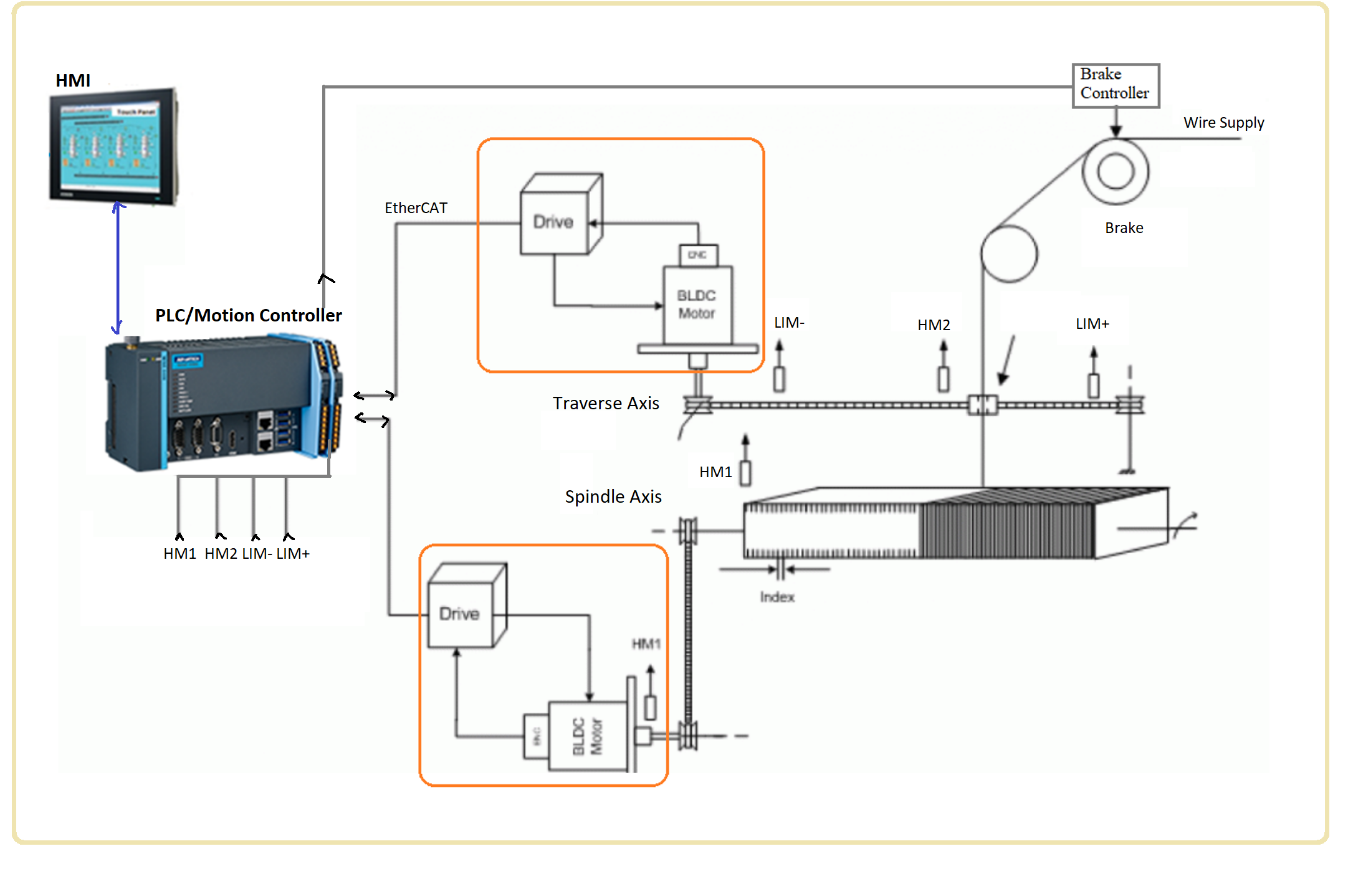
Fig. 1 – Coil winding machine: motion control automation.
Components of the motion control system include
- HMI – Flat Panel PC
- PLC/Motion Controller
- Two Servo Axis: Two servo motors with encoders and drives
- Proximity sensors for homing of Axis 1 and Axis 2, and LIM+ and LIM2 sensors for traverse axis (Axis 2).
- (Optional) Tension control system for wire supply roll, i.e. using a brake/clutch mechanism.
Maximizing acceleration capability of traverse axis is the determining factor how fast the coil can be produced per unit time. It determines the productivity of the machine. To that end, we exercise the following design practices: ,
- select servo motor with high torque to inertia ratio,
- design the motion transmission mechanism to be as low inertia as possible
- minimize backlash, friction and friction in the motion system in order to minimize their effect on high performance response (to reduce the effect of these on slowing the closed loop system position control bandwidth).
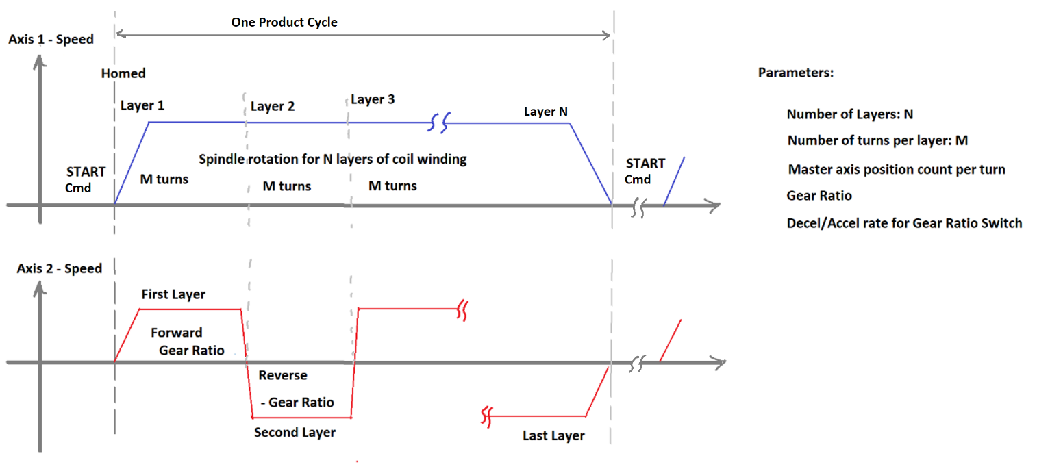
Helical Type Coil Winding Applications: Motion Coordination– electronic gearing (Fig. 2).
If the helical coil pitch is constant, the electronic gear ratio between Axis 1 (spindle) and Axis 2 (traverse/ carriage axis) is constant.
If the helical coil pitch is variable, then the electronic gear ratio is variable as function of the winding turn and position of spindle within one turn.

Fig. 2 – Coil winding machine automation logic for motion control: helical coil winding.
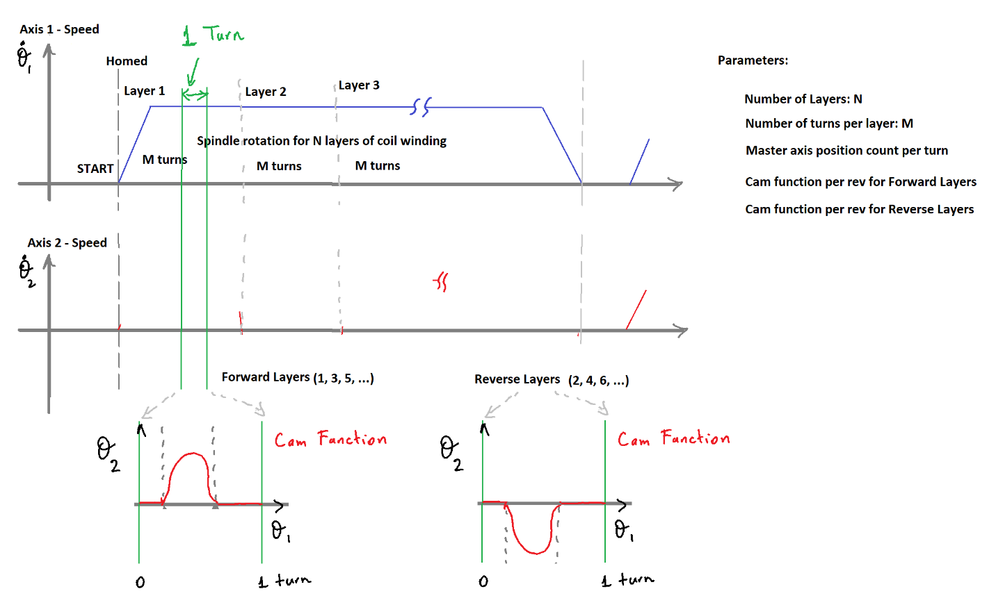
Slotted Type Coil Winding Applications: Motion Coordination – electronic caming (Fig. 3).
Electronic camming is effectively a more generalized version of electronic gearing in that we can considered as a variable electronic gear ratio for motion coordination.
In more complicated applications, we can further define a unique cam function for each turn of the whole winding operation.

