Reciprocating Flying Cutter Applications
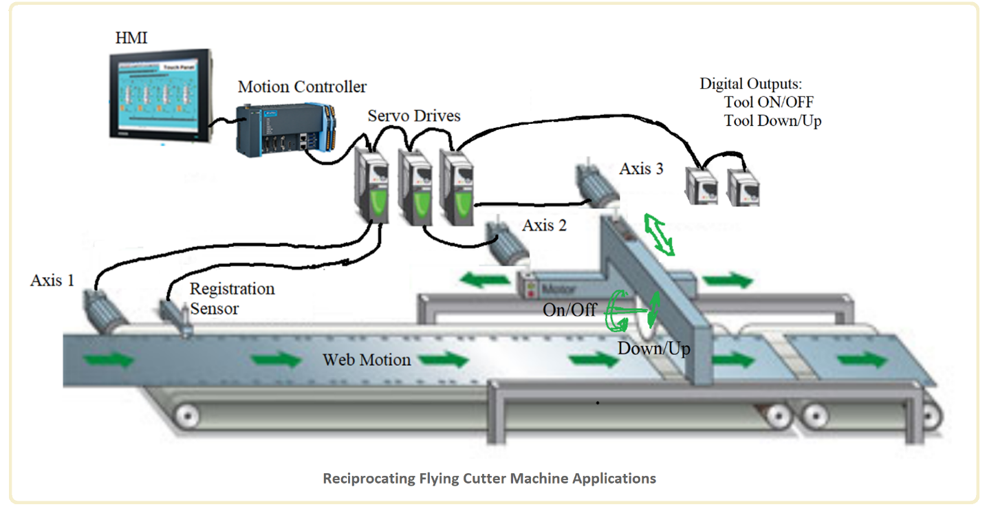
Reciprocating flying cutter application is used in web handling machines that involve cutting, pressing, embossing, printing operations on a moving web (Fig. 1). The motion control involves three axes: one axis is the web axis which is the Master Axis motion and two axis motion control of the tool; that is along the web and across the web..
Axis 1: Master Axis, web motion. This axis may be controlled by a servo motor whose position sensor (encoder) is used as the Master Axis. Alternatively, it may be controlled by another motor by an independent separate control system and that we measure the position and speed of the web by a Master Encoder.
Axis 2: Reciprocating, translational movement of the tool to match the speed of the web during processing and return motion.
Axis 3: Cross-translational movement of the tool to do its work, i.e. cut, write, print, emboss etc. In some applications, this axis may not be needed in that the motion of the tools may be just an DOWN/UP move using an digital output.

Fig. 1 – Reciprocating flying cutter machine applications.
Components
- HMI PC
- PLC/Motion Controller with EtherCAT I/O Modules
- Servo Drives and Motors for Axis 1, Axis 2 and Axis 3 (optional)
- Digital Inputs: Registration Sensor
- Digital Outputs: Turn ON/OFF tool, Tool DOWN/UP, i.e. for tool rotation motor, to move the tool up and down (Optional). The coordinated motion control problem is as follows:
Starting position: all three axes are homed.
Auto Cycle Begin:
- Axis #2 is geared to Axis #1, with gear ratio #1; match speed in A distance of Axis#1 while Axis #2 moves A/2 distance.
- Web moves: Axis #1 motion commanded to start a motion to run at constant speed, with a defined acceleration. Master encoder (either the encoder of the servo motor for web motion or independent master encoder) is used to measure the web motion. As a result of the gearing, Axis #2 also moves.
- At a registration sensor trigger: the Axis #2 position is captured, error between captured and desired position is calculated, and this position error correction motion is added to the gear motion. Registration position correction of Axis # 2 is defined to be completed within a defined distance of the Axis #1, so that slow down or speed up in the line speed does not affect the synchronization.
- Then Axis #3 moves a certain distance (cross-sectional length) of the web plus a small amount extra, at a desired motion profile (i.e. constant speed) within a certain motion distance of the Axis #1.
- Axis #3 motion of the tool returns to the start position within another motion distance of the Axis #1.
- Axis #2 motion: either waits until Axis #3 return motion is completed or make the move simultaneously based on selected option; move using gear ratio 2 to go back to start position.
- In addition, we have two digital output to ON/OFF actuators:
Parameter for each: Enable/Disable, ON Position, OFF position.
The function block logic turns ON/OFF these two outputs at the defined positions of Master axis when in Auto Mode.- Turn ON/OFF the rotation of the tool (i.e. circular saw): If this option is enabled, two parameter that defines the position of the master axis (Axis #1 or Axis #2) at which we turn it ON and OFF must be provided as inputs via HMI in Setup Mode.
- Up/down motion of the tool: down during cutting, up during non cutting.
If this option is enabled, two parameter that defines the position of the master axis (Axis #1 or Axis #2) at which we turn it ON (DOWN) and OFF (UP) must be provided as inputs.
This motion can also be more flexibly handled using a z-axis (Axis 4) servo motor drive system.
